Aiding Frames
The Aiding Frame Configuration (0x13,0x01) command enables the user to mount an External Aiding Sensor at a desired location on the vehicle and to specify the parameters of that frame. This includes an offset vector and a rotation with-respect-to the vehicle frame, eliminating the need to calculate complex frame transformations for the aiding data. These frames account for the effect of vehicle dynamics on external aiding measurements and their errors can be tracked during runtime.
Example: Configure external GNSS, downward facing radar, external magnetometer, optical flow sensor
SensorConnect
-
Open SensorConnect
-
Connect the 3DM-CV7-GNSS/INS to your computer
-
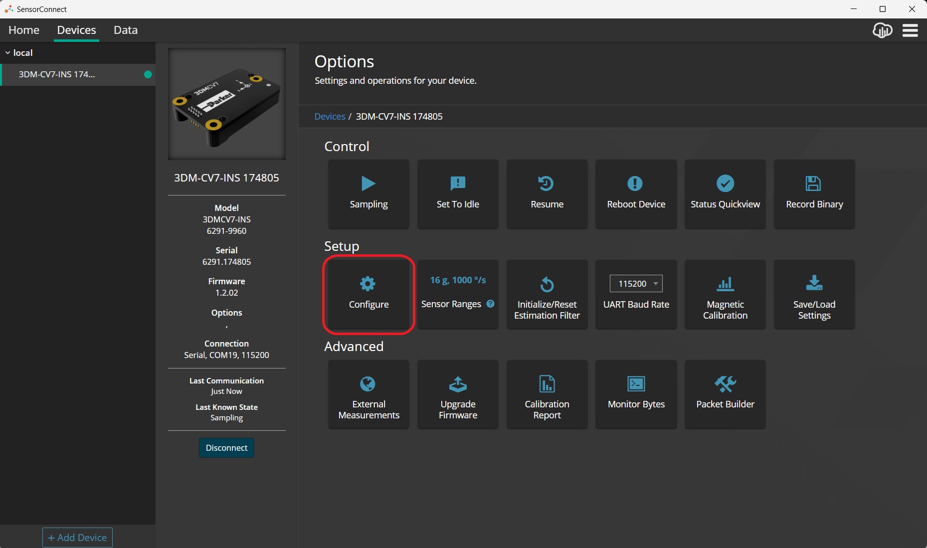
Enter the Configure tile
-
-
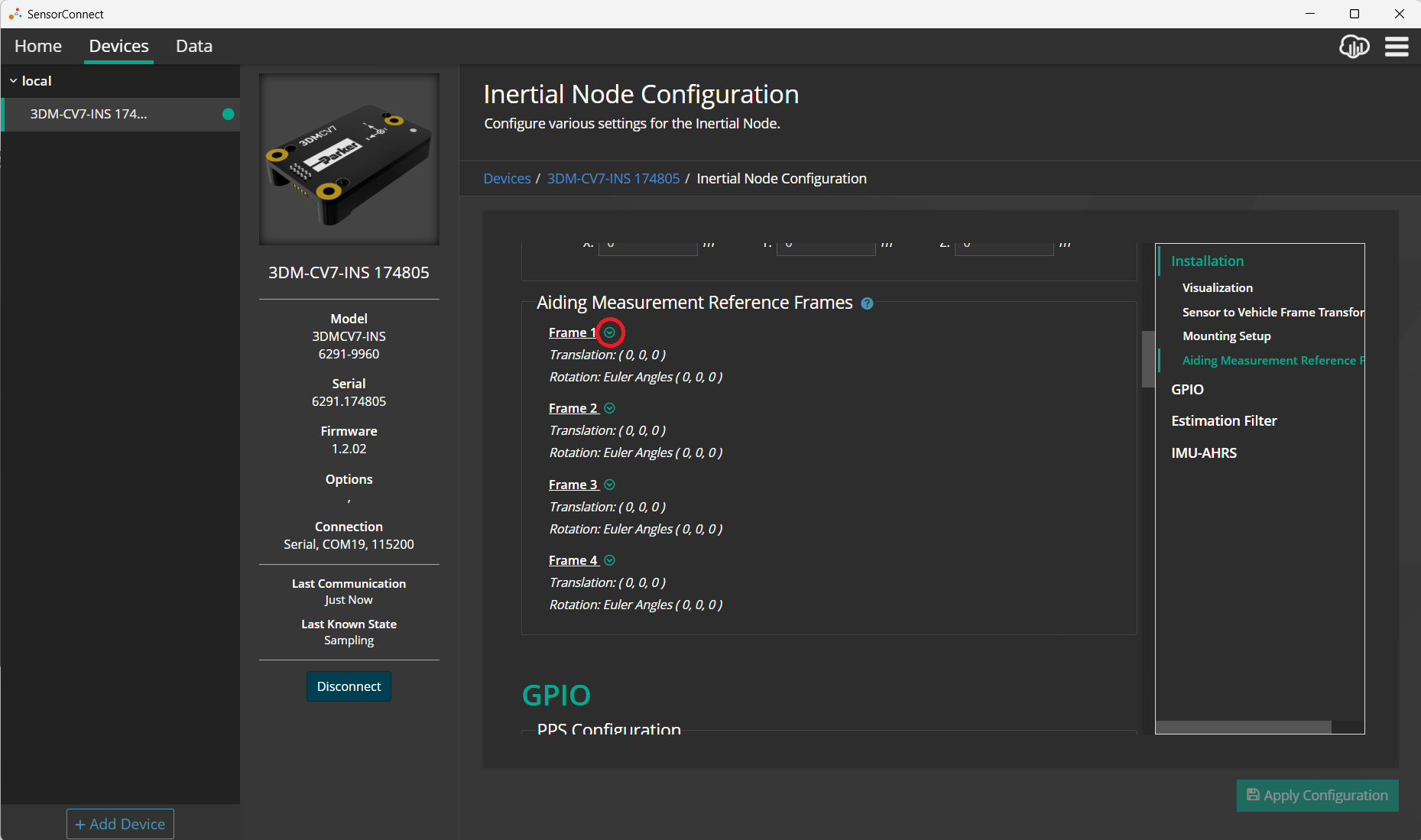
Scroll down to the Installation > Aiding Measurement Reference Frames section
-
Click the Frame 1 down carrot to show the aiding frame configuration fields
-
-
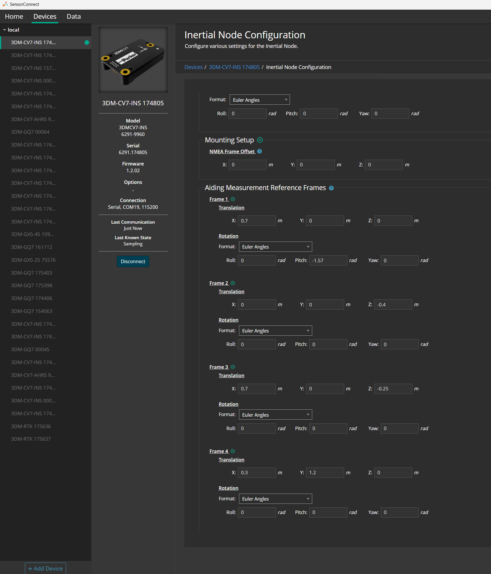
Assign each sensor a Sensor ID and a Aiding Frame as appropriate
-
Enter the Translation and Rotation for Sensor 1 in Frame 1, Sensor 2 in Frame 2, ...
-
-
-
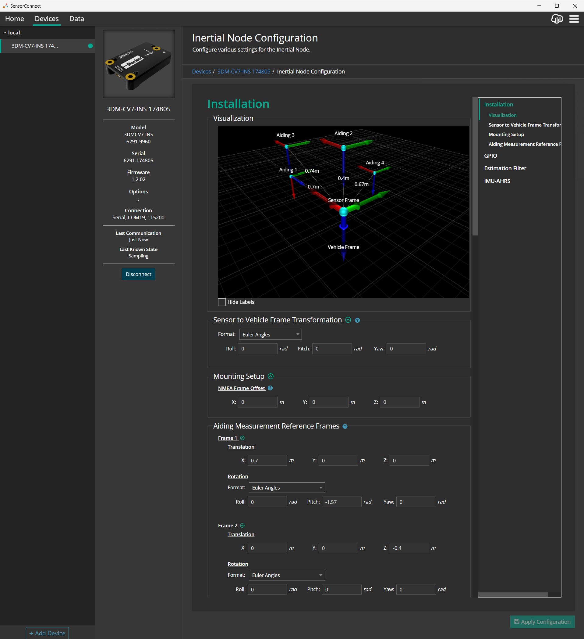
Verify the Translation and Rotation values are correct by scrolling up to view the Installation > Visualization window:
-
-
Click Apply Configuration
-
Save Settings to Non-Volatile Memory:
-
If you intend for this configuration to be persistent through power cycles or if the device will be power cycled before connecting to the external GNSS receiver, it is recommended to "save as startup settings" before removing power. This can be performed using the Device Settings (0x0C,0x30) command with the SAVE function selector. For instructions using other interface methods, refer to the FAQ: Do settings get erased from the 3DM-CV7-GNSS/INS if I unplug it?
-
-
MIP SDK
The Software page contains a link to the MIP SDK Github, which has examples of the 3DM-CV7-GNSS/INS's aiding frames in use.
ROS
ROS employs aiding frames through the use of Transforms. This is described in detail on the microstrain_inertial_driver ROS Wiki Transform page.